API 570 EXAM STUDY GUIDE
API 571 STUDY GUIDE
Read the previous part of API 570 STUDY GUIDE Series. You have to go through the relevant portion of the code for thorough understanding on the topic.
4.2.16 of API 571 : Mechanical Fatigue
Description Of Damage
Mechanical Fatigue - Fatigue cracking
Mechanical form of degradation
This happens when a component is exposed to cyclic stress
Sudden, unexpected failure occurs
Stresses can rise from 1) Mechanical loading 2) Thermal Cycling.
Affected Materials
All engineering alloys.
Critical Factors
Geometry, Stress level, number of cycles and material properties (strength, hardness, microstructure)
Design of the component is the most important factor.
Fatigue cracks usually initiate from surface. Grinding marks, tool marks etc are initiation points.
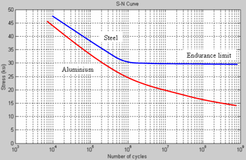
Alloys with endurance limit - Titanium, Carbon Steel and Low alloy steel. Below endurance limit fatigue cracking will not occur, regardless of the number of cycles.
Endurance limit / UTS = 0.4 to 0.5 or other wise, endurance limit = 40% - 50% of UTS
Materials without endurance limit: 300 Series Stainless Steel (SS), 400 Series SS, Aluminium and most other non-ferrous alloys.
 |
| Image taken from Wikipedia, CLICK HERE |
Inclusions found in metal can have an accelerating effect on fatigue cracking.
Finer grained microstructures tend to perform better than coarse grained.
Affected units or equipment
Thermal Cycling: Coke drums, Auxiliary boiler
Mechanical Loading: Pressure Swing Absorbers on hydrogen purification units, rotating shafts of centrifugal pumps and compressors., vibration of small diameter piping
Appearance or Morphology Damage
The signature mark of a fatigue failure is a "calm shell" type finger print that has concentric rings called "beach marks" emanating from the crack initiation site.
Cracks nucleating from surface stress concentration or defect = single "calm shell" finger print.
Cyclical overstress of a component without significant stress concentration - multiple points of nucleation = multiple "calm shell" finger print.
Microscopic yielding - The component is momentarily cycled above its yield stength.
Below is the image of a calm shell.
 |
| Image from WIKIPEDIA, CLICK HERE |
 |
| Click here for the original source of this image |
 |
| Click Here for the original source of the image |
Prevention/Mitigation
The best defense is a good design.
Minimize grinding marks, nicks and gouges on the surface of components.
Use low stress stamps and marking tools
Inspection and Monitoring
As fatigue crack initiates from the surface, surface detection NDT methods to be adopted. PT, MT and SWUT can be used to detect fatigue cracks at known areas of stress concentration.
Vibration monitoring for shafts
Related Mechanism
Vibration induced fatigue
LECTURES ON MECHANICAL FATIGUE
Questions and Answers↴
The questions and answers are for the evaluation of your understanding on the subject. You have to read the relevant portion of the code for answering these questions.
This blog is not a replacement for the training provided by authorized partners/experienced institutions nor this blog guarantee success in API exams. This blog is the outcome of the approach followed by the author for the preparation of API exams.
Disclaimer: Photos are taken from different websites. If this violates any copyright rules this will be removed. Please inform me if any of the photos or contents violate copyright rules. (through 13hareesh13@gmail.com). This blog is meant for educational purposes only. If it is used for any other means without the written consent from the author, the author will not be responsible. The author does not guarantee the accuracy of the data used in this blog. All the information, data, photo/image, calculations presented in this blog should be used at the sole risk of the user. The blogger is not liable or responsible in any way for any damage, losses or costs arising from the use of the blog for any purpose whatsoever or whosoever it may be. The blog is to be used at your sole risk and responsibility.

Comments
Post a Comment